Modern excavators and heavy machines rely on electronic control modules that constantly exchange information. These modules, often referred to as electronic control units, function as embedded computers that monitor inputs, process data, and command outputs such as valves, injectors, and actuators. They communicate with other modules using dedicated communication networks, most commonly the CAN-bus.
By the “Communication Lost” signal, it is indicated that the digital conversation has been interrupted due to internal issues and restoring the same requires careful, step-by-step diagnosis.
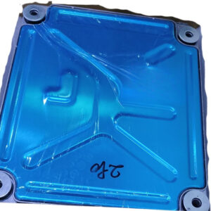
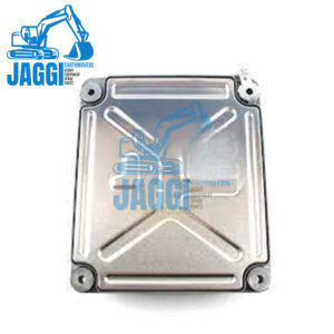
Decoding the controller’s role
The 14594707 controller works in tandem with a larger electronic system, thus exchanging signals with sensors, operator controls and other modules in it. Each controller comes with a microcontroller, memory and a communication interface that allows it to send and receive data. The process of communication exchange determines if the machine responds correctly to operator inputs and maintains safe, efficient operation. If the communication fails, the machine enters a limp mode with disabled functions.
What “Communication Lost” actually suggests
The CAN bus is essentially a shared wiring network that connects multiple controllers. Instead of individual wires running between each component, all modules communicate over two twisted wires known as CAN-High and CAN-Low. If either of these wires is damaged, disconnected, or electrically unstable, communication stops. The diagnostic system then reports that communication with the controller has been lost.
Maybe the controller itself has not failed and the problem lies inside the communication path, instead of the controller itself.
Common Causes of CAN-bus Communication Failure
One of the most frequent causes is wiring damage, since they operate in rough environmental conditions and are exposed to moisture, vibration, and heat. Over time, wiring insulation may wear out, connectors may loosen, or corrosion may develop at connection points.
Poor or unstable power supply integration is one of the key reasons that trigger improper voltage or ground and prevent seamless communication. Even a slightly weak ground connection can create unstable communication.
Termination resistance issues can also disrupt communication if the CAN network does not have proper resistance, resulting in communication failure.
Approach practically for the diagnostics
Diagnosis should always begin with visual inspection. Checking connectors, harness routing, and signs of physical damage often quickly reveals the issue. Loose connectors should be reseated, and damaged wiring repaired.
Measuring CAN-bus voltage and resistance is another important step. Proper readings confirm whether the network itself is healthy. If readings are abnormal, the fault likely lies in the wiring or another connected module.